
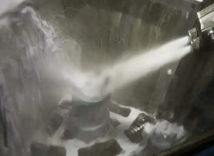
Additive manufacturing makes complex geometry possible, but the surface leaving the build process may still need cleaning and finishing. Residual powder and an uneven printed texture create different post-processing tasks, each affected by the material and the part’s geometry.
Wet blasting combines water and abrasive media to clean accessible surfaces and develop an initial, more even finish. It belongs within a defined post-processing route, with separate decisions for support removal, internal cleaning and any later machining or finishing.
Post-Processing Tasks
Separate the Post-Processing Tasks
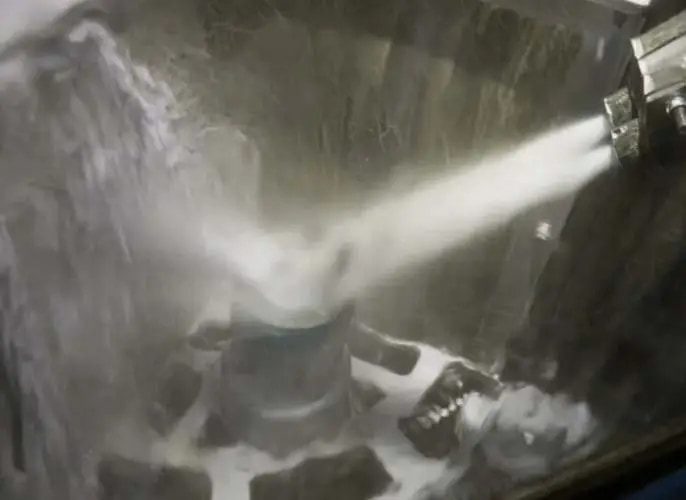
The starting point is the condition of the printed component, rather than a general request to make it smooth.
- Residual Powder: Identify where powder remains and whether the treatment stream can reach and leave those areas.
- Surface Texture: Identify the faces requiring refinement, their starting condition and the permitted change to the part.
- Support Structures: Establish the required support-removal operation and the condition in which the component will enter wet blasting.
Residual powder and solid supports need different removal decisions. Select a separate operation for detaching solid supports, then define how the remaining support-contact areas will be finished. This gives the wet blasting stage a clear incoming condition and a specific surface-treatment task.
Part Geometry
Let Geometry Define the Treatment Area
An exposed outer face and a deep internal passage are different cleaning problems. Nozzle access, part orientation and the escape route for water, media and removed powder influence what can be treated and subsequently cleaned.
Complex external shapes may be approached from several directions or presented in a fixture. For enclosed cavities, lattice interiors and narrow channels, assess both access and a route for removing the released material. These internal features need their own cleanliness criteria.
Thin walls, fine edges and small details also place limits on allowable surface change. Develop the treatment around those features and identify protected areas on the drawing. Evaluate them for dimensional and surface changes during the sample assessment.
Surface Finish
Surface Finish on Accessible Printed Faces
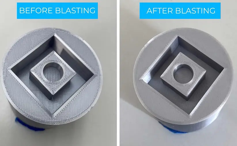
The comparison shows a change in the visible texture of a printed sample. Its circular and square features offer several faces for discussing the intended finish. These appearance examples do not establish a measured roughness result or the cleanliness of hidden features.
If roughness is specified, define the target and the surfaces where it applies. Evaluate the treated sample against that requirement and the dimensional limits. AM materials and build processes can produce different starting surfaces, so the selected finish needs to be evaluated on the intended workpiece.
Rinsing, drainage and drying also belong in the route. The required final cleanliness determines how remaining powder, media and water are assessed after blasting.
Equipment Selection
Match Equipment to Accessible Complex Parts
The CP1800 Wet Blasting Equipment for Complex Parts explicitly names 3D printed components in its original product description. Its documented role is degreasing and cleaning complex workpieces, with cleaning and rinsing and a clamping arrangement adapted to the part.
This makes it a relevant equipment reference for discussing fixture-based cleaning. The part envelope, fixture contact points, nozzle access and handling arrangement define the proposed setup. Define support removal, internal cleaning and the finished-surface criteria separately within the overall post-processing route. The wet blasting equipment overview provides context for comparing this fixture-based format with other handling approaches.
Your Application Brief
Define the Part Before Defining the Finish
An application brief should include the material, AM process, drawing or sample, incoming photographs and support-removal status. Mark the faces needing treatment, delicate or protected features, internal passages and any drainage restrictions.
Add the appearance or measured finish requirement, dimensional limits, cleanliness criteria and expected quantities. Together, these details distinguish an external surface-finishing task from a more demanding internal-cleaning problem and give the equipment discussion a practical basis.